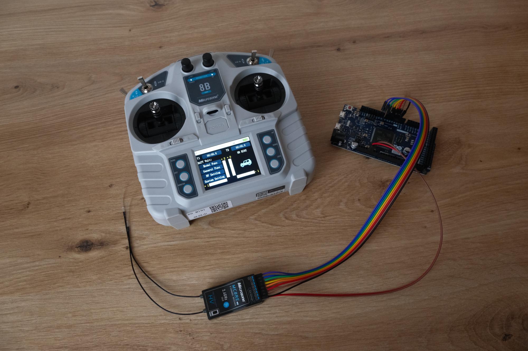
To read multiple PWM signals in Arduino and without blocking, we need to go beyond pulseIn function, which reads only one PWM input and blocks the loop’s execution until completion of PWM read.
This guide approaches the goal by using interrupts to read all 7 PWM signals from MC8RE without blocking the execution of the loop - by storing timestamps about pin state changes and derived durations with tiny interrupt handling functions, called Interrupt Service Routines.
Disclaimer: This how to is intended for advanced users. You should be able to understand what commands are doing, before copy-pasting and executing them.
Prerequisites
Ingredients needed:
- Arduino Due,
- MC8B-mini - remote,
- MC8RE-V2 - receiver for remote,
- jump wires - male to male, and male to female.

Notes:
- a different Arduino model might work, but this how to was not tested on them.
- a different compatible remote could work, but this how to was not tested on them.
- a different compatible receiver could work, but this how to was not tested on them.
Wiring
Powering MC8RE-V2 via Arduino:
- “positive electrode” to Arduino’s 5V:
- caution: check with your manual, mine states power supply to be of 4.5V to 6V,
- “negative electrode” to Arduino’s GND.
Providing signals from MC8RE-V2 to Arduino:
- connect PWM signal PINs for channels 1..7 to Arduino’s digital inputs 2..8.
Note: this just a bare minimalistic setup.
Reading PWM using Interrupts
The core of non-blocking approach is to execute code only if change on pin state happens (LOW from / to HIGH).
For this, we will create an interrupt event handling function and use attachInterrupt to associate the handling function.
The sketch for minimal 1 PWM read via interrupts:
volatile unsigned long lastRaising;
volatile unsigned long durationUp;
volatile unsigned long durationCycle;

const int channelPin = 2;

void setup() {
  Serial.begin(9600);

  pinMode(channelPin, INPUT);

  attachInterrupt(digitalPinToInterrupt(channelPin), onChangeInterrupt, CHANGE);
}


void loop() {
  Serial.print("PWM ");
  Serial.print(durationUp);
  Serial.print("/");
  Serial.print(durationCycle);

  Serial.println();
  Serial.println();

  delay(250);
}

void onChangeInterrupt() {
  unsigned long current_micros = micros();
  int state = digitalRead(channelPin);

  if (state) {
    durationCycle = current_micros - lastRaising;
    lastRaising = current_micros;
  } else {
    durationUp = current_micros - lastRaising;
  }
}
Full solution - 7 channels
For the full solution, I’ve decided to create:
- reusable class
InterruptPWMTracker, - constant number of channels (PWM inputs) read -
channelCount, - constant array with pin numbers for channels -
channelPin, - array of
InterruptPWMTrackerinstances to be able to access them in loop / by index.
The sketch for reading all 7 PWM signals read via interrupts:
class InterruptPWMTracker {
  public:
    volatile unsigned long lastRaising;
    volatile unsigned long durationUp;
    volatile unsigned long durationCycle;

    const int pin;
    void(*callback)(void);


    InterruptPWMTracker(int pin, void(*callback)(void)):
      pin(pin),
      callback(callback)
    {}

    void setup() {
      pinMode(pin, INPUT);
      attachInterrupt(digitalPinToInterrupt(pin), callback, CHANGE);
    }

    void updateFromPinChangeInterrupt() {
      unsigned long current_micros = micros();
      int state = digitalRead(pin);

      if (state) {
        durationCycle = current_micros - lastRaising;
        lastRaising = current_micros;
      } else {
        durationUp = current_micros - lastRaising;
      }
    }
};

const int channelCount = 7;

// this has cyclic depedendency on callback functions, so will be initialized after them
extern InterruptPWMTracker channels[channelCount];

void setup() {
  Serial.begin(115200);

  for (int i = 0; i < channelCount; i++) {
    channels[i].setup();
  }
}

void loop() {
  for (int i = 0; i < channelCount; i++) {
    if (i > 0) {
      Serial.print(" ");
    }

    printChannelToSerial(i);
  }

  Serial.println();
  Serial.println();

  delay(50);
}

void printChannelToSerial(int number) {
  Serial.print("CH");
  Serial.print(number + 1);
  Serial.print(" ");
  if (channels[number].durationUp < 1000) {
    Serial.print(" ");
  }
  Serial.print(channels[number].durationUp);
  Serial.print("/");
  Serial.print(channels[number].durationCycle);
}

void channel1onChangeInterrupt() {
  channels[0].updateFromPinChangeInterrupt();
}

void channel2onChangeInterrupt() {
  channels[1].updateFromPinChangeInterrupt();
}

void channel3onChangeInterrupt() {
  channels[2].updateFromPinChangeInterrupt();
}

void channel4onChangeInterrupt() {
  channels[3].updateFromPinChangeInterrupt();
}

void channel5onChangeInterrupt() {
  channels[4].updateFromPinChangeInterrupt();
}

void channel6onChangeInterrupt() {
  channels[5].updateFromPinChangeInterrupt();
}

void channel7onChangeInterrupt() {
  channels[6].updateFromPinChangeInterrupt();
}


InterruptPWMTracker channels[channelCount] = {
  InterruptPWMTracker(2, channel1onChangeInterrupt),
  InterruptPWMTracker(3, channel2onChangeInterrupt),
  InterruptPWMTracker(4, channel3onChangeInterrupt),
  InterruptPWMTracker(5, channel4onChangeInterrupt),
  InterruptPWMTracker(6, channel5onChangeInterrupt),
  InterruptPWMTracker(7, channel6onChangeInterrupt),
  InterruptPWMTracker(8, channel7onChangeInterrupt),
};
The output is something like this:
...

CH1 1599/14000 CH2 1026/14000 CH3 1986/14000 CH4 1064/14000 CH5  992/14000 CH6  992/14000 CH7 1989/14000

CH1 1980/14000 CH2 1315/14000 CH3 1980/14000 CH4  982/14000 CH5  992/14000 CH6  993/14000 CH7 1993/14000

CH1 1977/14000 CH2 1624/14000 CH3 1653/14000 CH4  981/14000 CH5  992/14000 CH6  993/14000 CH7 1989/14000

CH1 1871/14000 CH2 1959/14000 CH3  976/14000 CH4 1044/14000 CH5  996/14000 CH6  996/14000 CH7 1989/14000

CH1 1482/14000 CH2 1999/14000 CH3  972/14000 CH4 1643/14000 CH5  993/14000 CH6  992/14000 CH7 1992/14000

CH1  979/14000 CH2 1873/14000 CH3  997/14000 CH4 1976/14000 CH5  995/14000 CH6  994/14000 CH7 1993/14000

CH1  988/14000 CH2 1326/14000 CH3 1738/14000 CH4 1776/14000 CH5  992/14000 CH6  992/14000 CH7 1989/14000

CH1 1169/14000 CH2 1046/14000 CH3 1984/14000 CH4 1474/14000 CH5  992/14000 CH6  993/14000 CH7 1989/14000

...
Demonstration
This video shows how it works:
Alternative - ESP32 programmed with Arduino
The code above works also on ESP32 with just pins change to:
InterruptPWMTracker channels[channelCount] = {
  InterruptPWMTracker(2, channel1onChangeInterrupt),
  InterruptPWMTracker(3, channel2onChangeInterrupt),
  InterruptPWMTracker(4, channel3onChangeInterrupt),
  InterruptPWMTracker(5, channel4onChangeInterrupt),
  InterruptPWMTracker(6, channel5onChangeInterrupt),
  InterruptPWMTracker(7, channel6onChangeInterrupt),
  InterruptPWMTracker(8, channel7onChangeInterrupt),
};
Demonstration with ESP32: